I Asked An Actual Apollo Engineer to Explain the Saturn 5 Rocket - Smarter Every Day 280
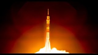
The Saturn V rocket is one of the most amazing vehicles ever created by humans
12 chapters
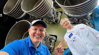
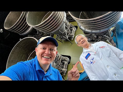
- Introduction to Luke Talley and the Saturn VApollo LegacyLuke Talley was one of the original IBM engineers on the Apollo program's Instrument Unit, the computer-shaped ring that steered rockets to the moon. He is an award-winning engineer who attended the Apollo 13 launch at Cape Kennedy on April 11, 1970.Personal Background• Born in Alabama after his father was killed in World War Two • Learned electronics by building crystal radios with community support • Used his father's G.I. Bill to study electrical engineering at University of Alabama • Married to Kitty, his partner throughout his engineering careerExpert KnowledgeLuke understands how all three phases of the Saturn V rocket work because the Instrument Unit he worked on had to control the entire rocket, including every component with pyro-detonators that needed precise firing sequences.Program OverviewThe video covers the first stage, second stage, third stage, launch escape system, and how the Instrument Unit controls all major components of the Saturn V.
- First Stage: F-1 Engines and Fuel Tank DesignEngine Power• Five F-1 engines producing 1.5 million pounds of thrust each • Four outer engines are gimballed and can move to steer the rocket • Center engine remains fixed for stability • Engines move within a five-degree circle to control pitch, yaw, and rollFuel CompositionEach engine burns one ton of kerosene and two tons of liquid oxygen per second. All five engines combined burn 15 tons of propellant every second, causing rapid changes in rocket mass that affect bending modes.Engine Cooling SystemFine tubes run through the thrust chamber walls where kerosene is routed to cool the engine before combustion. The throat temperature reaches 5,900 degrees Fahrenheit, hot enough to melt any unprotected material. Inconel metal (nickel, cobalt, chromium) provides corrosion resistance.Tank Structure• Fuel tank made of aluminum plate 1.25 to 1.75 inches thick • Smooth sections hold kerosene fuel • Corrugated sections reduce weight while maintaining structural strength • Automated welding required 20 to 30 passes with extreme precision
- First Stage: Injector Design and Cooling SystemsFuel InjectionThe injector plate has about 6,000 holes with some spraying kerosene and others spraying liquid oxygen. Without baffles, the fuel mixture would create circular rotating motion at about 2,000 RPM, causing dangerous instability.Combustion Stability• Swirling fuel can create acetylene torch effect that cuts through the nozzle bell • Unbalanced fuel mixture causes engine vibration strong enough to shake the rocket apart • Baffles break swirling motion into smaller, more stable areas • Baffles affect only the first few inches inside the engine from the injectorNozzle CoolingThe turbine runs on a fuel-rich mixture with exhaust temperature around 1,200 degrees. This exhaust is captured and routed around the nozzle extension walls, then injected into the nozzle interior for cooling while directing the thrust backward.Thermal ProtectionInconel tubes carry coolant through the combustion chamber. Insulating blankets cover engines and the base to keep heat within the engines instead of dumping it on the center engine, which sits in a low-pressure zone created by forward motion.
- First Stage: Propellant Tanks and SeparationTank Architecture• Kerosene fuel tank is the lower smooth section • Liquid oxygen tank is the upper smooth section with about a 2 to 1 volume ratio • Oxygen is 9 pounds per gallon; kerosene is 7 pounds per gallon • Liquid oxygen lines run through the fuel tank like a thermos bottle with inner and outer walls and low-pressure gas insulationStructural ForcesAll forces from engines transmit through the tank skin with no internal beams. The fuel tank must withstand both upward force from engines and internal pressure. The corrugated inner tank areas only need to withstand upward force.Separation Sequence• Main Engine Cut Off (MECO) shuts down all engines • Ordnance explosively severs tension straps holding stages together • Eight solid rocket motors on the fins slow the first stage • Eight ullage rockets on the interstage push the second stage forwardFlight PerformanceFirst stage burns for 2.5 minutes, reaching 40 miles altitude and 5,000 miles per hour. During separation at 70 miles altitude, the first stage eventually impacts the Atlantic Ocean about 450 miles from Cape Kennedy.
- Second Stage: J-2 Engines and Hydrogen FuelEngine Specifications• Five J-2 engines producing 230,000 pounds of thrust each • Four outer engines are gimballed, one center engine is fixed • Each engine burns about 600 pounds of propellant per second • Five J-2 engines equal the power of one F-1 engine with less massHydrogen Challenges• Liquid hydrogen is 426 degrees below zero Fahrenheit • Hydrogen is extremely light at 0.7 pounds per gallon • Hydrogen pumps must spin at 37,000 RPM compared to oxygen pump at 8,000 RPM • Much more efficient than kerosene but far more difficult to handleTank DesignSecond stage uses a common bulkhead between hydrogen and oxygen tanks, saving tremendous length and weight compared to separate tanks. Phenolic honeycomb grid filled with foam provides exterior insulation to prevent boil-off from the extremely cold hydrogen.Flight DurationSecond stage burns for approximately 6 minutes, accelerating the payload to 115 miles altitude and 15,500 miles per hour. The stage eventually breaks up in the atmosphere, with debris landing about 2,000 to 2,500 miles from Cape Kennedy.
- Third Stage: Single Engine and Orbital InsertionEngine Configuration• Single J-2 engine for the third stage • Engine can pitch and yaw but cannot roll independently • Auxiliary Propulsion System (APS) provides roll control with hypergolic fuel • APS uses nitrogen tetroxide and hydrazine that ignite on contact without ignitersThermal ManagementThird stage has internal insulation on the tank to maintain hydrogen temperature during extended flight. Unlike the second stage that burns quickly, the third stage coasts in orbit for hours before reignition.Orbital Mechanics• First burn takes payload to 117 miles altitude at 17,500 miles per hour into Earth orbit • Spacecraft coasts in parking orbit for about 1.5 to 2 hours • Second burn accelerates payload to 24,500 miles per hour toward the moon • Third stage burns for about 2 minutes per burnDiameter ProgressionFirst two stages are 33 feet in diameter, third stage and Instrument Unit are 22 feet in diameter, and the spacecraft is 11 feet in diameter. Luke notes this elegant progression of 33, 22, 11 was convenient for Alabama engineers working on the program.
- Spacecraft Configuration and Launch Escape SystemComponent Stack• Launch escape system at the very top with solid rocket motor • Command module houses the three astronauts • Service module beneath the command module • Spacecraft Lunar Module Adapter (SLA) contains the lunar moduleEmergency Abort SystemEmergency Detection System hardware in the Instrument Unit monitors engine performance. If two engines fail or vibration rates become too high, the system automatically fires the launch escape motor to pull just the command module 30,000 to 40,000 feet higher, then deploys parachutes for crew recovery.Launch Escape Tower• Solid rocket motor has thrust equivalent to a Redstone rocket but shorter burn duration • Nozzles point outward to avoid damaging the spacecraft above • Conical protective cover shields the spacecraft until jettison • Tower separates during second stage burn with small auxiliary motors to pitch it awaySpacecraft SeparationAfter lunar module extraction, the command and service modules separate from the third stage. The Auxiliary Propulsion System fires to slow the third stage, creating separation velocity to prevent collision during the three-day coast to the moon.
- Instrument Unit: The Brain of the RocketLocation and PurposeThe Instrument Unit sits on top of the third stage, a large ring-shaped computer that controls all three rocket stages through cables running down through the interstages. It handles guidance, navigation, engine gimballing, pyrotechnic sequencing, and separation timing.Control Functions• Reads guidance platform 25 times per second • Compares actual position to planned trajectory • Determines required pitch, yaw, and roll corrections • Closes the loop system continuously throughout flightCable ManagementCables connect the Instrument Unit to other stages through interstage sections. Disconnects allow stages to separate cleanly, and backup guillotine blades ensure cable severance with explosive ordnance to prevent the first stage from hanging onto subsequent stages.Design PhilosophyThe Instrument Unit distributes weight around the outside ring to control center of gravity. This modular design intended to support future Apollo Applications Program experiments through interchangeable thermal panels and moveable equipment.
- Third Stage Disposal: Moon Impact vs Solar OrbitEarly Missions StrategyOn early Apollo missions, the third stage was slowed by 85 miles per hour and sent past the trailing edge of the moon, placing it in solar orbit. This avoided cluttering lunar orbit and kept debris away from future spacecraft.Apollo Lunar Science• Beginning with Apollo 12, astronauts left Apollo Lunar Surface Experiment Packages (ALSEP) on the moon • Primary objective was determining the moon's interior composition • Researchers wanted to know if the moon had a molten core like Earth • Scientists discovered the moon has mass concentrationsControlled ImpactsStarting with Apollo 13, the Instrument Unit slowed the third stage by only 45 miles per hour instead of 85, causing it to slam into the moon. These 10 to 11 ton impacts created moonquakes lasting 2.5 to 3 hours that helped scientists study the moon's interior structure.Trajectory PrecisionThe Auxiliary Propulsion System on the third stage executed these maneuvers under Instrument Unit control. Engineers preprogrammed exact firing durations to achieve the specific velocity changes needed for either solar orbit or lunar impact.
- Apollo 12: The Space Junk MysteryTracking ErrorApollo 12's tracking system miscalculated the rocket's velocity, believing it was traveling faster than it actually was. Mission controllers commanded an additional 25-mile-per-hour slowdown beyond what was already programmed, overshooting the target.Orbital Capture• Third stage missed the moon by several thousand miles • Entered very high Earth orbit approximately 70,000 miles by 500,000 miles • Over subsequent years, Earth's and moon's gravity stretched the orbit • Orbit eventually extended beyond the Lagrange L1 point where solar and Earth gravity balanceRediscoveryIn 2002, an amateur astronomer spotted a white dot that appeared to be an asteroid. JPL scientists, particularly Dr. Paul Chodas, recognized the object's trajectory matched the Apollo 12 third stage and calculated it was returning to Earth orbit after 30 years in solar orbit.Future ReturnsJPL simulations predict the object, designated J002E3, will continue cycling between solar and Earth orbits every approximately 40 years for the next 1,000 to 2,000 years. Eventually it will collide with Earth or the moon, potentially creating a spectacular impact event.
- Luke Talley's Career and LegacyApollo Program ExperienceAt the peak of the Apollo program, 300,000 contractors and 47,000 NASA employees worked on the Saturn V rocket. Many young engineers like Luke came directly from college with little prior computer or digital experience, learning on the job across RF technology, telemetry systems, and environmental control.Technology Evolution• Started with transistors and analog electronics in the 1960s • Moved to digital computer systems and flight control • Worked on Skylab control systems with 24/7 mission support • Eventually transitioned to machine learning and handwritten check recognition at IBMCareer PathAfter the Apollo program wound down, Luke worked on the Patriot missile program, then moved to North Carolina for IBM's commercial division. IBM sent him back to school for a computer science degree, and he spent his final IBM years developing one of the first widespread commercial machine learning applications.Legacy ImpactLuke's 51-year career spanning early spaceflight to machine learning exemplifies the broader impact of Apollo. The engineers and contractors who worked on Saturn V applied their pioneering knowledge across aerospace, computers, and emerging technologies that shaped modern industry.
- Conclusion: Witnessing HistoryMoon Landing MomentWhen Neil Armstrong stepped out of the spacecraft during Apollo 11, Luke watched on television. His daughter was blocking his view, so he had to ask her to move over slightly to see one of humanity's greatest achievements that his work made possible.Team ContributionLuke emphasizes that while he was an important engineer on the Instrument Unit, he was just one part of the broader Apollo effort involving over 350,000 people. His humility reflects the collaborative nature of the space program's success.Personal SupportLuke wanted to acknowledge his wife Kitty, who recently passed away. She was a driving force throughout his career, enabling his work much as Destin's wife Tara supports his projects. Her role in Apollo's success deserves recognition.Educational MessageLuke expressed sadness that the Apollo program's achievements and the learning experience of 300,000 young engineers haven't been promoted more widely. He encourages viewers to recognize that government space programs developed a generation of innovators who later contributed to diverse fields.