The Computer that Controlled the Saturn V (Behind the Scenes ft Linus Tech Tips) - Smarter Every Day
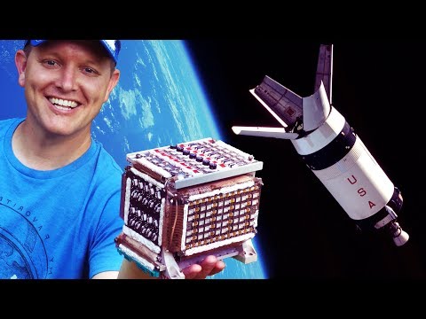
A memory module for the Saturn 5 launch vehicle digital computer
11 chapters
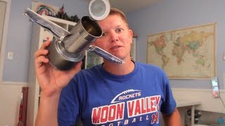
- Introduction to the Saturn V ComputerChannel OverviewDestin from Smarter Every Day introduces the second channel where he takes in-depth technical looks at various subjects, focusing on the Saturn V launch vehicle digital computer.Key Guests• Destin (host) - interested in rockets and spacecraft • Linus (Linus Tech Tips) - computer expertise • Luke Talley - IBM engineer who worked on Apollo during the 1960s and 1970sMain TopicDeep exploration of the LVDC memory module and how the computer systems controlling the Saturn V rocket functioned.Physical HardwareA logic card made from special magnesium-lithium alloy to save weight, representing some of the first miniaturized transistor technology used in space.
- Memory Module Design and ConstructionPhysical BitsThe computer used ferrite cores (small iron rings) to store data. Wires were threaded through these cores by hand, with magnetization direction determining whether a bit was a 1 or 0.Memory Specifications• One module contained approximately 100 kilobits of memory • Eight modules made up the complete system • Total capacity: 112 kilobytes for the entire computer • Hand-threaded wires connected to magnetic cores on circuit boardsManufacturing ProcessPrimarily women workers with textile industry experience hand-wove the memory cores using copper wire, tweezers, and extreme patience to ensure proper alignment and prevent kinks or bends.Assembly ChallengeThe intricate hand-assembly process was so complex that it would be nearly impossible to replicate today, despite being considered cutting-edge technology in the 1960s.
- Logic Cards and Component TechnologyCard ArchitectureLogic cards plugged into the LVDC and performed processing functions rather than expanding memory. The OVC had 35 modules per side (70 total) with heat sinks for thermal management.Transistor Design• Each module contained 2-8 discrete transistors • Transistors measured approximately 25 thousandths of an inch (1/32 inch) square • No integrated circuits were used in the LVDC • Modules used T-squared L technologyManufacturing TechniqueAluminum oxide substrates were printed with conductor patterns like t-shirts, fired in an oven, then transistors were mounted on solder balls aligned by surface tension and melting in another oven cycle.Resistor PrecisionResistors were hand-trimmed using ultrasonic scribes to achieve exact values, scraping away conductive material until precise resistance was reached, then coated with protective red material.
- Core Memory Deep DiveHow Core Memory WorksMagnetic cores required pushing current through wires to magnetize them in specific directions. Reading destroys the magnetization, so data had to be written back immediately after reading.Memory Module Capacity• Each plane contained 8,192 cores • 14 planes stacked to create one module • Two memory modules in the Saturn V computer • Each module held 16,000 words of memoryRedundancy SystemDuring Saturn flights, both memory modules executed the same flight program in parallel and compared outputs. If outputs differed, the computer used a subroutine to determine which value made most sense.Reliability RecordDuring all Saturn flights, there were fewer than 10 memory compare mismatches, demonstrating remarkable reliability for a hand-assembled system without integrated circuits.
- Flight Data Analysis MethodsData RetrievalFlight data was transmitted as telemetry and collected by ground stations around the world, then routed through Goddard Space Flight Center to IBM's team for analysis.Analysis Process• Data received as octal dumps on 11 by 17 inch fan-fold paper • Printouts contained 10-bit octal numbers in 40 columns and 30 rows • Engineers created templates by hand-cutting known values to identify anomalies • Templates were slid down the printout page by page to find problemsManual ConversionOnce problematic frames were identified, octal numbers were manually converted to decimal values and cross-referenced with calibration charts to determine actual measurements like temperature.Problem SolvingEngineers compiled data over multiple weeks, plotted graphs by hand, and sometimes discovered the identified issue wasn't actually the problem, requiring the analysis to start over.
- Computer System ArchitectureDesign HeritageThe LVDC was derived from the ASC-15 Titan missile computer that IBM developed, using a combination of digital and analog systems rather than purely digital architecture.Core Functions• Navigation and guidance calculations • Control of engine timing (start, stop, fire) • Separation and retro-rocket firing commands • Steering and rocket pointingOperating SystemThe computer ran a major 2-second loop executing navigation-guidance-control repeatedly, with interrupt handlers for time-sensitive tasks like platform readings (25 times per second) and valve commands.Memory-Based SchedulingNo built-in CPU scheduler existed. Instead, switch selector commands and timers stored in memory acted as a manual scheduler, triggering interrupts at specific flight times for critical actions.
- Gyroscope and Sensor SystemsGuidance PlatformSpinning mass gyroscopes floated in pressurized nitrogen gas (3,000 psi) instead of ball bearings to minimize friction and drift, with nitrogen supplied by compressed gas bottles and regulators.Drift Management• Gyroscope friction causes apparent motion detection that the computer interprets as real movement • Computer uses 2-second major loop comparisons to check against stored flight profiles • Platform 25 Hz readings (every 40 milliseconds) help detect and correct drift errors • System relied on pre-flight calibration of drift rates rather than in-flight recalibrationRate GyroscopesSecondary gyroscopes measured actual vehicle rotation rates in X, Y, Z axes, outputting pulses that the digital computer summed to determine velocity through integration of acceleration.Accuracy TradeoffRate gyroscopes were less accurate than the guidance platform but the platform had superior long-term accuracy. For the 6-11 minute boost phase, the platform-based navigation proved sufficient without in-flight star tracking.
- Thermal Management SystemCooling ArchitectureThe instrument ring divided into three sections: navigation/guidance control (bottom third), telemetry packages (top), and environmental/power systems. Anodized aluminum plates with internal passageways pumped coolant through components.Power Dissipation• LVDC dissipated approximately 100 watts • OVD-A dissipated approximately 190-200 watts • Individual logic cards dissipated 85-90 watts • Each aluminum plate dissipated about 420 watts totalSublimator TechnologyA gray sublimator box with micro-porous sintered metal allowed water to freeze in the vacuum of space, with ice subliming directly to vapor for cooling without requiring a compressor.Operational CycleCoolant temperature cycled between 50-60 degrees Celsius. Computer sent commands to open the water valve when temperature exceeded 60 degrees, closing it again at 50 degrees, requiring only small amounts of water for 11-12 hour missions.
- Telemetry and Command SystemsCommunication Hardware• VHF and UHF telemetry on early versions • S-band transponder at 2200-2282 megahertz • Power amplifier and coaxial switches • High-gain, low-gain, and two omnidirectional antennasData TransmissionHigh-gain and low-gain antennas required pointing toward ground stations for strong signals, while omnidirectional antennas provided weaker but omnidirectional coverage. Telemetry included octal dumps of computer data for analysis.Command CapabilitiesDuring boost phase, no commands could be sent due to rapid events. Once in orbit, Houston could send commands through the transponder to recirculate stages, update navigation, or modify flight parameters on the LVDC.Lunar Impact TrackingOn Apollo missions 13-17, the instrument unit crashed into the moon as science objective. Engineers added extra battery to track the transponder signal all the way to lunar impact, correlating impact time with seismometer data.
- Lunar Science and LegacyMoon Impact DataInstrument unit impacts with the moon equaled approximately 11 tons of TNT, producing moonquakes lasting 2.5 hours that were recorded by seismometers left on the lunar surface.Core ResearchApollo mission seismometer data initially appeared too noisy to analyze. Six to eight years before the video, Dr. Renee Weber's group at Marshall Space Flight Center used modern signal processing to re-analyze the old data.Moon Composition DiscoveryCleaned seismic data revealed the moon possesses a liquid iron core similar to Earth, surrounded by a layer of molten material, with additional layers still cooling gradually over geological time.Closing RemarksThanks to Mark from rocketrelics.org for loaning hardware samples, thanks to Linus Tech Tips for collaborating, and appreciation for viewers supporting Smarter Every Day through subscriptions and patronage.